November 12, 2024
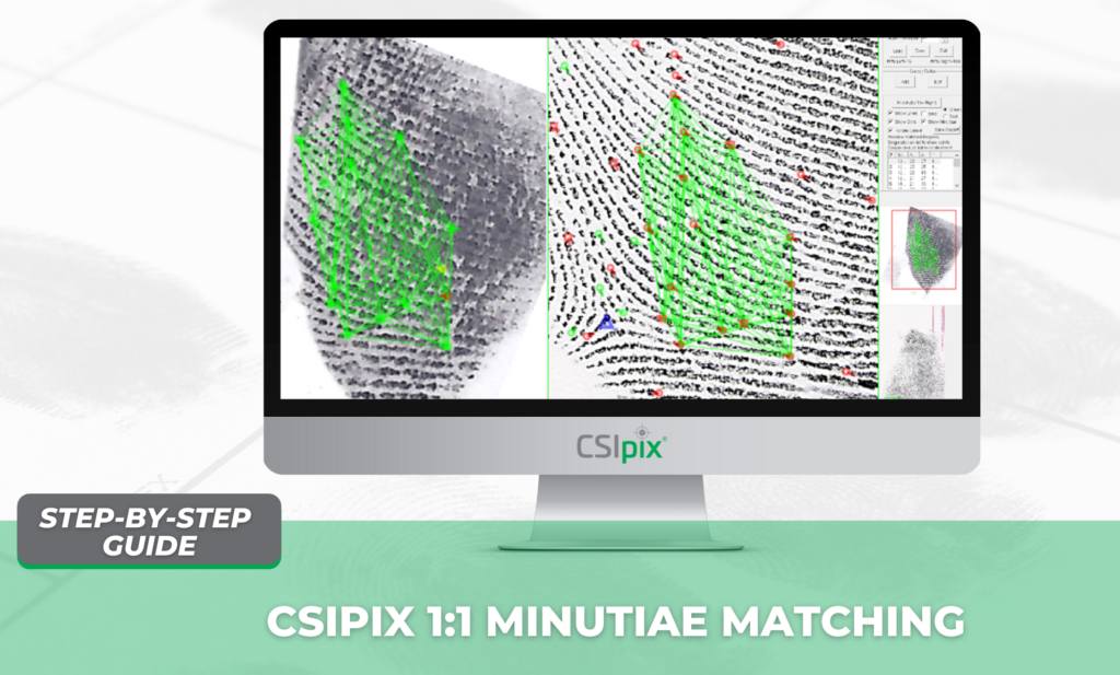
Take the guesswork out of locating key minutiae—saving you valuable time, especially with complex palm and other latents that lack an “anchoring” feature.
Welcome to this step-by-step guide on using Comparator Pro’s 1:1 automated minutia pattern matching function. Comparator Pro incorporates everything in both Comparator and Matcher, combining all the necessary tools into one software application.
Let’s dive into how these two functions can enhance your workflow, save you time, and help reduce missed identifications.
Step 1: Load a Latent image on the LEFT side.
Step 2: Calibrate the Latent image, if necessary.
Step 3: Resample the Latent image to be between 300 and 2000 dpi, if necessary.
Step 4: Enhance the Latent image, if necessary. Save the calibrated and enhanced image.
Step 5: Annotate visible minutia points on the Latent print using Ridge Ending symbols and/or the bifurcation symbols. Ridge endings and bifurcations are interchangeable for the matcher algorithm. You have the option to use GYRO colors for your minutia point annotations. See Figure 1. Note: You need to tag at least four points to run the Match (left to right) function.
Step 6: Annotate visible cores and deltas on the Latent. In the example, there are no visible cores or deltas.
Step 7: Archive the features you saw prior to opening a Known Image for future reference and documentation. Click File -> Save -> Left Image. Make sure to save the image with the annotations merged for this purpose.
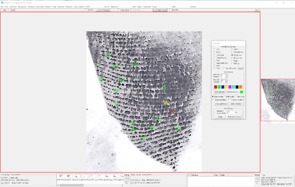
Figure 1: Latent Image
Step 8: Load a Known print on the RIGHT side. See Figure 2.
Step 9: Calibrate the Known image, if necessary.
Step 10: Resample the Known image to be between 300 and 2000 dpi, if necessary.
Step 11: Enhance the Known image if necessary. Save the resulting image, so that you do not need to repeat these steps in the future.
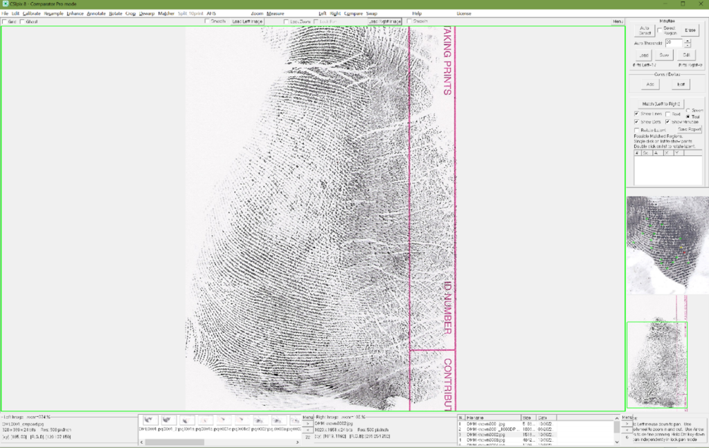
Figure 2: Known Image
Step 12: Click “Matcher” on the menu bar to open the Matcher Docker. Run the Auto Detect algorithm on the Known print. To do this: make sure the Known print is selected (it has a green border) and click the “Auto Detect” button. The algorithm will analyze the print and place ridge ending and bifurcation symbols where it found them. See Figure 3. The minutia detection algorithm can run on a greyscale image or a color image. In both cases, ridges must be darker than the regions between ridges. The default threshold is 20, this is appropriate for most inked and livescan prints. For very messy inked prints it may be appropriate to use a higher threshold, like 35. If you want to run the algorithm on a section of the image, check “Select Region” button and draw the region of interest on the image, then click the “Auto Detect” button.
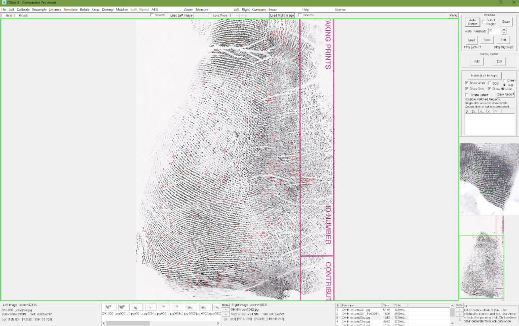
Figure 3: Minutia points found using “Get Minutiae” function with threshold = 20.
Step 13: Optionally, click the “Edit” button in the Minutiae section of the docker or go directly to Annotate and fix mistakes made by the Auto Minutia Detection algorithm. Remove false positives, add missed points and move points if necessary. See Figure 4, manually added minutiae points are shown in green (any color can be used).
Step 14: Add cores and deltas to the known image. Cores and deltas will speed up the Matcher algorithm as it restricts the regions searched. They will also reduce the occurrence of false positive matches. Note: they won’t help with the above latent, because it does not have any cores or deltas, but we suggest tagging and saving them for future searches.
Step 15: Save the Right min file so that you will not have to tag minutia points, cores and deltas on this Known when running for future searches. File -> Save -> Right min file.
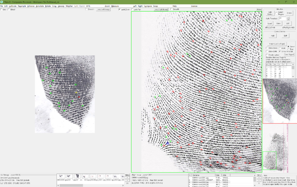
Figure 4: Latent and Known Images.
In the Known image, automatically detected minutia are red and manually tagged minutia are green.
Step 16: To search the Known print for minutia patterns that match the tagged minutiae pattern on the Latent, click “Compare” on the menu bar so that two images are visible. Click the “Match (Left to Right)” button in the Matcher docker. When the Matcher algorithm has finished a list of possible matched regions will appear, sorted by match score. By default, the top scoring region will be displayed, see Figure 5. To look at other regions, left click on the entries in the list. Double click on an entry to rotate and align the Latent image appropriately. Tip: click Lock Pan right after double clicking to have the two images rotationally aligned and aligned in the x and y directions.
Step 17: If the known region displayed is potentially a matching region, you can do any of the following – remove the green lines, remove the green dots, bold the green lines or dots, remove all minutia points – then continue with your manual comparison to determine if the regions match.
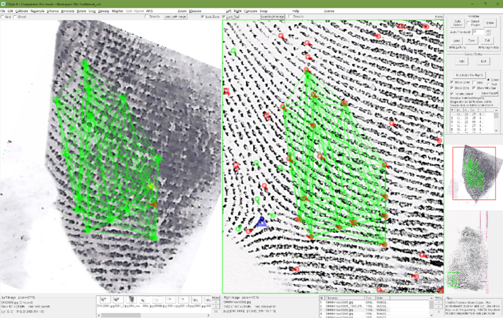
Figure 5: Top scoring pattern found on the Known print
Minutia Detection Function Tips:
The maximum number of bifurcations and ridge endings allowed is 2000. If you run the automated minutiae detection algorithm on a palm, foot or a full tenprint and the number of bifurcations or ridge endings exceeds 2000 you will see an error message. If this happens, you can use the “Select Region” option to run the algorithm on only a portion of the image.
After running the Auto Detect function check around cores and deltas for missed minutia points. Check around the edge of the print for missed points. Also check for missed bridges, island ridges and spurs.
False positives commonly occur along creases and in other regions where ridge flow is unclear. If you have a region with a great deal of false positives you can use the Select Region and “Erase” button on the Matcher docker, to clear the region.
Additional Tips:
If you tag cores on a known print make sure to tag them all.
If you tag deltas on a known print make sure to tag them all.
Follow along with this quick video to see the steps in action and get a feel for the features.
